Lithium Battery Manufacturing
2021-07-02
Cell Assembly
In the best factories cell assembly is usually carried out on highly automated equipment, however there are still many smaller manufacturers who use manual assembly methods.
The first stage in the assembly process is to build the electrode sub-assembly in which the separator is sandwiched between the anode and the cathode. Two basic electrode structures are used depending on the type of cell casing to be used, a stacked structure for use in prismatic cells and a spiral wound structure for use in cylindrical cells.
See Cell Constuction for a description of Stacked and Wound cells.
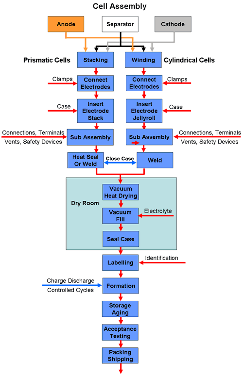
The assembly process for prismatic and cylindrical cells is illustrated in the following diagram.
Prismatic Cells
Prismatic cells are often used for high capacity battery applications to optimise the use of space. These designs use a stacked electrode structure in which the anode and cathode foils are cut into individual electrode plates which are stacked alternately and kept apart by the separator. The separator may be cut to the same size as the electrodes but more likely it is applied in a long strip wound in a zig zag fashion between alternate electrodes in the stack.
While this case design makes optimum use of space when used in a battery pack, it has the disadvantage that it uses multiple electrode plates which need a clamping mechanism to connect all the anodes together and to the main terminal post and a similar mechanism for the cathodes. This all adds to the complexity and labour content of the cell and consequently to the costs.
Some prismatic cells are also made by the simpler method of winding the electrodes on a flat mandrel. (See below)
Stacked electrodes are also used for the production of pouch cells.

For cylindrical cells the anode and cathode foils are cut into two long strips which are wound on a cylindrical mandrel, together with the separator which keeps them apart, to form a jelly roll (Swiss roll in the UK). Cylindrical cells thus have only two electrode strips which simplifies the construction considerably.
A single tab connects each electrode to its corresponding terminal, although high power cells may have multiple tabs welded along the edges of the electrode strip to carry the higher currents.
The next stage is to connect the electrode structure to the terminals together with any safety devices and to insert this sub-assembly into the can. The can is then sealed in a laser welding or heating process, depending on the case material, leaving an opening for injecting the electrolyte into the can.
The following stage is to fill the cell with the electrolyte and seal it. This must be carried out in a "dry room" since the electrolyte reacts with water. Moisture will cause the electrolyte to decompose with the emission of toxic gases. Lithium Hexafluoride (LiPF6) for instance, one of the most commonly used electrolyte materials, reacts with water forming toxic hydrofluoric acid (HF).
Afterwards the cell is given an identification with a label or by printing a batch or serial number on the case.


