


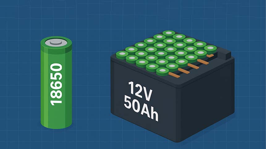
Quick summary (direct answer): To build a practical 12V 50Ah lithium-ion pack using 18650 cells you will choose a 4S configuration and a parallel count between 15 and 17 depending on per-cell capacity and safety margin — resulting in approximately 60 to 68 individual 18650 cells. This guide expands every engineering step, design choice, test protocol, manufacturing method, and compliance requirement so you (or your engineering team) can implement or verify the pack design.
Table of contents
- Basic cell physics and nomenclature
- Series vs parallel math — detailed worked examples
- Energy and power calculations (Wh, W, C-rate)
- BMS selection and protection topology
- Thermal management & mechanical layout
- Cell welding, interconnects, and pack assembly
- Testing, QC, and recommended test protocols
- Certifications and transport regulations
- Cost, sourcing and supplier checklist
- Degradation, cycle life modelling and warranty planning
- Case study / sample BOM
- FAQ
1. Basic 18650 cell physics and nomenclature
“18650” denotes the can size (18 mm diameter × 65.0 mm length). Cells vary by chemistry; NCA/NCM chemistries offer high energy density while LiFePO4 emphasizes safety and cycle life. Nominal voltage per cell of NCM/NCA is 3.6–3.7V. In battery pack design, two independent axes govern your design:
- Series (S): adds voltage. For a 12V nominal system, 4 cells in series (4S) is standard (3.6V × 4 = 14.4V nominal).
- Parallel (P): adds capacity (Ah) and current capability. Each cell in parallel contributes its Ah to total pack Ah.
Why "12V" is actually a 14.x V nominal system
Many end users call systems “12V” for convenience. Lithium-ion systems nominally sit higher (12.8–14.4V). Design chargers and protective circuits using the pack's fully-charged and cut-off voltages (4.2V × 4 = 16.8V max charge).
2. Series vs. Parallel math — detailed worked examples
We provide step-by-step math with rounding rules, safety buffers, and considerations for manufacturing tolerance.
Definitions and formulas
Given: Desired pack capacity = 50 Ah. Nominal cell capacity = C_cell (Ah). Cells in series = S. Cells in parallel = P. Then:
Total Pack Voltage (nominal) = S × V_cell_nominal
Pack Capacity (Ah) = P × C_cell
Total Cells = S × P
Total Energy (Wh) = Pack Voltage_nominal × Pack Capacity
Worked example A — using 2600 mAh cells
Cell capacity = 2.6 Ah. P required = 50 ÷ 2.6 ≈ 19.23 → round up to 20 for margin. Total cells = 4 × 20 = 80 cells. Pack nominal energy (assuming 3.6V nominal) = 14.4V × 50Ah = 720 Wh.
Worked example B — using 3000 mAh cells
Cell cap = 3.0 Ah. P = 50 ÷ 3.0 ≈ 16.67 → round up to 17. Total cells = 4 × 17 = 68 cells. This is commonly used in industry for cost-performance balance.
Worked example C — using 3500 mAh cells
Cell cap = 3.5 Ah. P = 50 ÷ 3.5 ≈ 14.29 → round up to 15. Total cells = 4 × 15 = 60 cells. High-energy cells reduce the cell count but typically cost more and may have different thermal behavior.
Rounding policy & safety margin
Always round parallel count up (never down) to ensure the nominal capacity meets or exceeds target. Add a small margin (3–7%) when specifying total pack Ah to account for capacity fade, manufacturing variance, and balancing inefficiencies.
3. Energy and power calculations (Wh, W, C-rate)
Important metrics:
- Wh (Watt-hours): energy content; Pack_Wh = V_nom × Ah
- C-rate: ratio of discharge current to capacity. A 1C discharge for a 50Ah pack is 50A.
- Max continuous current: number of parallels × per-cell max continuous current (cells often rated for 1–3A continuous for high-capacity cells, premium high-drain cells up to 10A+).
Example: power for a 4S17P pack using 3000 mAh cells
- Per-cell max continuous discharge = 2C (hypothetical) → 3.0Ah × 2 = 6A per cell
- Parallel groups = 17 → pack continuous ≈ 17 × 6A = 102 A
- At nominal 14.4V → continuous power ≈ 14.4V × 102A = 1,468.8 W
4. BMS selection and protection topology (deep)
BMS selection is critical for safety and reliability. Key capabilities:
- Cell balancing (passive vs. active)
- Overcharge/over-discharge protection at cell level
- Over-current and short-circuit detection
- Temperature monitoring and dynamic derating
- Communication (UART/CAN/SPI) for telemetry and integration
Balancing methods
Passive balancing: dissipates extra charge as heat via shunt resistors. Simpler and cheaper; adequate for small packs.
Active balancing: transfers charge between cells, improving efficiency and balancing speed—recommended for large packs or packs requiring long-life and tight SOC matching.
BMS architecture examples
Common architecture for 4S50Ah:
- BMS board with 4 cell sense inputs, dual MOSFETs for charge/discharge isolation, NTC sensor(s) for thermal cut.
- Optional pre-charge resistor for soft-start inrush control when connecting capacitive loads (inrush management).
- External high-current contactor or fuse for protection in high-energy applications.
Recommended protective thresholds
| Parameter | Recommended Value |
|---|---|
| Overcharge per cell | 4.25V ± 0.03V |
| Over-discharge per cell | 2.7–2.8V |
| Over-current (short) | dependent on application — typically 2–6× continuous rating |
| Operating temperature | -20°C to 60°C (design-dependent), charging 0–45°C preferred |
5. Thermal management & mechanical layout
Heat is the main driver of degradation and safety incidents. Key practices:
- Leave small air channels between parallel stacks or use thermal pads.
- Place NTC sensors near the highest heat region — often the center of a parallel group.
- Design housings with thermal conduction paths; metal plates (isolated electrically) can act as heat spreaders.
Thermal simulation & worst-case scenario
Conduct an FEA thermal simulation for continuous discharge and a worst-case internal short. Ensure cell surface temperatures remain below 60–65°C under design loads; above this, cycle life falls quickly and thermal runaway risk increases.
6. Cell welding, interconnects, and pack assembly
Connection methods:
- Spot welding (nickel strips) – most common for high-reliability packs.
- Soldering – acceptable for small assemblies with low heat exposure but risks cell damage due to heat conduction.
- Tab welding + rivets – used in some industrial processes.
Nickel strip selection
Choose nickel strip thickness based on current. Typical thickness ranges from 0.15mm to 0.4mm. Wider strips reduce resistance but increase mechanical stiffness; design for uniform pressure on welded joints.
Welding quality inspection
Use a pull-test and visual inspection for welds. Measure joint resistance — a consistent low resistance across welds ensures balanced current paths.
7. Testing, QC, and recommended test protocols
Recommended tests for each production batch:
- Cell incoming inspection (capacity, internal resistance, visual)
- Cell matching and grouping by Ah and resistance
- Weld pull tests and continuity
- Formation cycles (initial charge/discharge to stabilize cells)
- Capacity verification (C/5 or C/3 test)
- Environmental stress tests: thermal cycling, vibration
- Safety tests: short circuit, overcharge, crush (if applicable to product category)
Sample test table: production QC checklist
| Test | Target / Pass Criteria |
|---|---|
| Cell capacity (batch) | Within ±5% of spec |
| Internal resistance | Within ±10% of batch median |
| Weld strength | > 25 N (example) |
| Pack capacity (final) | ≥ 50 Ah (after formation) |
| BMS function | Over/under-voltage, balancing correct |
8. Certifications and transport regulations (overview)
Common battery-focused certifications / standards to reference for export and industrial sales:
- IEC 62133 — cell/pack safety tests for portable batteries.
- UN38.3 — transport testing for lithium batteries.
- UL 1642 / UL 2054 / UL 2580 — may apply depending on region and product.
- RoHS / REACH — environmental restrictions.
For shipping by air or sea, follow IATA / IMO guidance — properly classify, package, label, and include shipper declarations.
9. Cost, sourcing and supplier checklist
When selecting a supplier, consider these items as minimum requirements:
- Cell certificates and traceability (lot codes)
- Pack-level certifications and test reports
- Warranty, RMA and field support
- Ability to customize BMS and mechanical housing
- MOQ tiers and lead times
Indicative BOM (example)
| Item | Spec / Example | Qty |
|---|---|---|
| 18650 cells (3000mAh) | 3.0Ah, 2.5–3.5A continuous | 68 |
| BMS | 4S, 100A continuous, passive balance, UART | 1 |
| Nickel strip | 0.2mm × 10mm | as needed |
| Housing & connectors | ABS + terminals | 1 |
| Heat shrink / foam / pads | thermal isolation | as needed |
10. Degradation, cycle life modelling and warranty planning
Common degradation drivers:
- High temperature exposure
- Deep discharges and high C-rate cycling
- Calendar aging (time + SOC)
- Mechanical stress and vibration
Modeling capacity fade (simple model)
As a basic model, capacity after N cycles can be approximated by:
C(N) = C0 × (1 - a × N^b)
Where a and b are empirical constants depending on chemistry and use case. For practical engineering, use manufacturer-provided cycle life curves and validate with accelerated aging tests.
11. Case Study: A&S Power 4S17P 12V 50Ah Prototype
Short summary of a real prototype we built for a medical device OEM:
- Cells: Samsung 30Q (3000mAh) — 4S17P = 68 cells
- BMS: Custom 4S 80A with UART telemetry and active temperature derating
- Thermal approach: central NTC with thermal pad and metal spreader
- Result: 51Ah measured after formation, continuous 60A delivery capability, passed IEC 62133 battery tests
This product was certified for medical accessory use and shipped to EU & US customers after passing UN38.3 for transport.
12. Frequently Asked Questions
Q1: Exactly how many 18650 cells do I need for 12V 50Ah?
Answer: Use formula P = 50 ÷ C_cell(Ah). With common cells: 3.0Ah → 17P → 68 cells total (4S17P). For 3.5Ah → 15P → 60 cells. Provide margin and round up.
Q2: Can I mix different capacity 18650 cells in one pack?
Answer: No. Mixing capacities, ages, or manufacturers is strongly discouraged — it leads to imbalance, accelerated degradation, and safety risks. Always use matched cells (same batch preferred).
Q3: What is the best way to balance cells in a 4S17P pack?
Answer: For packs of this scale, passive balancing is common. For improved life and uniformity, consider active balancing especially when cell variance exists or life requirements exceed 1,000 cycles.
Q4: What is the expected weight and volume?
Answer (approximate): 18650 cells energy density ~200 Wh/kg. For ~700 Wh, theoretical cell weight ~3.5 kg; pack including BMS, housing, connectors ~4.5–6 kg depending on mechanical design.
Q5: Are 18650 cells still recommended in 2025?
Answer: Yes. 18650 cells remain widely used due to mature supply chains and proven reliability. Newer formats (21700, pouch cells) offer alternatives; choose format based on system constraints (energy density vs space vs cost).
Q6: How should I specify warranty?
Answer: Typical industrial warranty: 1–3 years or a defined cycle count (e.g., 500 cycles to 80% SOH). For medical or safety-critical applications, tighter SLAs and field support are required.
Q7: How do I derate for temperature?
Answer: Reduce maximum continuous current as cell temperature rises; implement conservative charge/discharge profiles above 45°C. Use thermal protection in BMS to reduce charge/discharge or cut off in high-temperature events.
Q8: What transport/packaging do I need for shipping internationally?
Answer: Follow UN38.3 testing and IATA Packing Instructions. Include correct labeling, state of charge limitations for air transport (commonly ≤30% SOC for some airline restrictions), and proper packaging to prevent short circuits.
Q9: How do I test for internal shorts or latent defects?
Answer: Use vibration and thermal cycling, dark field visual inspection, ultrasonic weld inspection (where available), and an electrical soak test at moderate C-rate to reveal weak welds or latent defects.
References
- UL 1642 — Battery Safety
- IEC Standards & IEC 62133
- UN / UNECE — Transport regulations (UN38.3)
- A&S Power — Custom Battery Solutions
Appendix A — Quick design checklists for engineers
- Confirm cell datasheet: Ah, internal resistance, max continuous & pulse current, recommended charge/discharge temps.
- Decide S × P based on cell capacity, cost, thermal, and weight trade-offs.
- Design BMS spec and communications (do you need CAN/UART?).
- Plan mechanical housing, airflow, and serviceability (replaceable modules?).
- Define test matrix: incoming QC, formation cycles, environmental tests.
Conclusion & Next steps
This guide outlines the full engineering path from the fundamental math to production-ready considerations for building a 12V 50Ah battery pack using 18650 cells. The practical range for total cells is 60–68, depending primarily on per-cell capacity selection (3.5Ah → 60 cells; 3.0Ah → 68 cells). For any production design, perform detailed thermal analysis, adopt robust BMS and QC processes, and ensure required certifications are obtained before field deployment.
If you’d like, we can take any of these next steps for you:
- Produce a manufacturing-ready BOM and mechanical drawing for a chosen S×P configuration.
- Run a thermal simulation and propose a heatsink/thermal pad layout.
- Design a BMS schematic (including recommended MOSFETs, fuses, and telemetry).
- Provide a factory-level QC and testing protocol document tailored to your SOC and application (medical / consumer / industrial).


")